- 您现在的位置:买卖IC网 > Sheet目录2000 > IDTNW6005ASG (IDT, Integrated Device Technology Inc)IC CALLER ID DECODER 20SOIC
13
INDUSTRIAL TEMPERATURE RANGE
NW6005 ENHANCED TYPE II CALLER ID DECODER
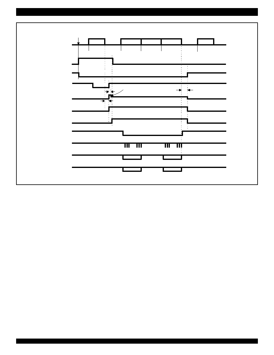
Alerting
Signal
Ch. Seizure
Mark
Message
Ring
..101010..
Data
...
A
B
C
D
E
F
G
Line Reversal
A/B Wires
PWDN
STD
TE DC load
TE AC load
FSKEN
CD
DR
DCLK
DATA
15 ±1 ms
20 ±5 ms
<120
A
50 - 150 ms
< 0.5 mA (optional)
Current Wetting Pulse
Zss
Tip/Ring
DT-ASEN
Note 1
Note 2
Note 3
Note 4
Notes:
1) A
≥ 100ms, B=88 - 110 ms, C≥ 45 ms (up to 5 sec), D= 80 -262 ms, E= 45 - 75 ms, F≤ 2.5 sec (typ. 500 ms), G≥ 200 ms.
2) By choosing t
GA=15 ms, tABS will be 15-25 ms (refer to Fig. 8). Current wetting pulse and AC/DC load should be applied right after the
STD rising edge.
3) AC and DC loads should be removed between 50-150 ms after the end of the FSK signal. The NW6005 may go to power down mode
to save power.
4) FSKEN should be set low to disable the FSK demodulator, when the FSK signal is not expected.
5) Tip/Ring DT-ASEN, PWDN and FSKEN are internal signals decoded from Control Bits CB2-0.
6) When CB0 is low, both DR and DCLK pins are unused.
Figure 13. BT Idle State (on-hook) Data Transmission Timing Diagram
Note 5
Note 6
发布紧急采购,3分钟左右您将得到回复。
相关PDF资料
IDTNW6006AS
IC CALLER ID DECODER 20-SOIC
IDTSSTE32882HLBBKG
IC REGISTERING CLK DRIVER 176BGA
IDTSSTE32882KA1AKG
IC REGISTERING CLK DRIVER 176BGA
ISD1750SYR
IC VOICE REC/PLAY 50SEC 28-SOIC
ISD5008EYI
IC VOICE REC/PLAY 4-8MIN 28-TSOP
ISL12008IB8Z
IC RTC I2C LO-POWER 8-SOIC
ISL12020MIRZ-T7A
IC RTC/CALENDAR TEMP SNSR 20DFN
ISL12022IBZ-T7A
IC RTC/CALENDAR TEMP SNSR 8SOIC
相关代理商/技术参数
IDTNW6006AS
功能描述:IC CALLER ID DECODER 20-SOIC RoHS:否 类别:集成电路 (IC) >> 接口 - 编码器,解码器,转换器 系列:- 产品变化通告:Development Systems Discontinuation 26/Apr/2011 标准包装:1 系列:- 类型:编码器 应用:DVB-S.2 系统 电压 - 电源,模拟:- 电压 - 电源,数字:- 安装类型:- 封装/外壳:模块 供应商设备封装:模块 包装:散装 其它名称:Q4645799
IDTP62000NLG
制造商:Integrated Device Technology Inc 功能描述:IC PWM CTRLR 2/3/4-PHASE 64QFN
IDTP62000NLG8
制造商:Integrated Device Technology Inc 功能描述:IC PWM CTRLR 2/3/4-PHASE 64QFN
IDTP63131-00NDGI
制造商:Integrated Device Technology Inc 功能描述:IC BUCK CTRLR MULTI-PH 40QFN
IDTP63131-00NDGI8
制造商:Integrated Device Technology Inc 功能描述:IC BUCK CTRLR MULTI-PH 40QFN
IDTP63133-00NDGI
制造商:Integrated Device Technology Inc 功能描述:IC BUCK CTRLR MULTI-PH 40QFN
IDTP63133-00NDGI8
制造商:Integrated Device Technology Inc 功能描述:IC BUCK CTRLR MULTI-PH 40QFN
IDTP67001EXG
制造商:Integrated Device Technology Inc 功能描述:IC MOSFET DVR 1PH VR12 8SOIC